RC Submarine: CPU System
CPU system
I am planning on using an AVR processor as the central processor in the submarine control. I have many years experience in working with AVR processors and it is perfect for the job. Besides all the control functions I also intend to build in a datalogger and an IIC menu system (as most of my other designs). My experience is that is takes some flash and ram resources, so I have decided to use an ATMEGA644 which have 64kbyte flash and 4kbyte ram, 32 I/O, 10bit A/D etc.
It should control:
- Diving system
- Pressure sensor (diving, emergency)
- Surveillance sensors: water, temperature, battery power, radio signal etc.
- Fold able diving planes
- Variously features: lights (LEDs), periscope
- Datalogger
- IIC interface for monitoring
Feature and resource overview
| Control | Functions | Resources |
| Dive system | Motor control (relay + control) | 1x I/O 1x PWM + (relay + FET) |
| Dive planes | Fold able planes (signal-in + servo) | 2x I/O |
| Surveillance sensors | Water | 1 x I/O |
| Periscope | Up/down control (signal-in + control) | 2x I/O |
| LEDs | 2 RED top warning LEDs | 1x I/O (FET) |
| Datalogger | Power measurement (V + A) | 1x A/D (1 already present) |
| IIC interface | Menu system | IIC port |
Radio control system
I am going to use my FF9 transmitter where I am replacing the frequency module with a 40MHz module. The receiver will be a 8 channel dual conversion crystal less receiver. (I couldn't find a 9 channel version)
Channel allocation
| Uses | Channels |
| Motor | 1 |
| Up/down planes | 1 |
| Rudder | 1 |
| Dive planes + fold | 2 |
| Dive (piston) | 1 |
| Periscope up/down | 1 |
| LEDs | 1 |
| Total | 8 |
All channels will be used :-|. If more features in the future are needed, then it might be possible to multiplex some of the channels like periscope and LED control.
Dive system control
Pressure sensor
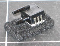
I have brought a pressure sensor on Ebay which is able to meassure 0-1bar (0-17 PSI) with comply to 10 meters of water. With the right electronics the depth can be found with a precision of app. 1cm.
The pressure sensor is a Honeywell SDX15D4. It have two probes where it measures the difference in pressure. I don't need that feature (but it was the only one I could buy), so I am just closing one of the probes and that should be fine.
The sensor is a little bit special, as it output a differential voltage of app. 60mV at 1 bar! There are two solution to that problem:
- Using an OP-AMP to amplify the signal (2-400 times)
- Using the ATMEGA build x200 A/D differential channels
I have chosen to go for the OP-AMP and then a 12bit external A/D converter. That should give me the resolution that I need.
Piston position and motor control
The piston position is handled by a resistor attached to the piston rod.
The motor control is made from a 10A FET and a relay to change the direction. In this way I am ably to control the piston very precise.
Water level
I have also included a water level device, so I can determinate if the sub is level or not. It is a digital accelerometer called Memsic 2125, which comes on a small PCB which is easily to attach to the CPU PCB. It output is a pulse where the duty cycle is changed according to the angel.
Surveillance system
Aux sensors:
- Temperature sensor
- Water sensor
The temperature sensor will be a LM35, as it is easy to attach to 'long' wires in a stable way.
The water sensor will just be a simple resistor measurement using an OP-AMP.
Datalogger
Entry time will be 1 sample pr. second (all sensors will be sampled 10 times pr. second but only saved once pr. second).
| Item | Method | Interval/resolution | Bits |
| Current (A) | Average | 0-10A (50mA) | 8 |
| Voltage (V) | Minimum | 4-9V (100mV) | 6-7 |
| Pressure | Average | 0-0.5bar (1mbar) | 9 |
| Piston position | Average | 0-100% | 7 |
| Total | 32 |
The flash has 32kbytes so that gives 8000 samples equal 8000 seconds or 2 hours.
Other single values of interest:
- Max current
- Total power used
- Minimum voltage
- Max temperature
- Number of seconds
Schematic
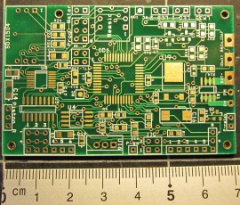
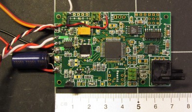
Here is the final schematic: akula_sub_sch.pdfIt is quite big and a bit complicated, but I really wanted it to control the whole sub and also have a few extra in and outs in case I had forgotten something.
Test
During the programming of the board I had a lot of noise problems coming from the long power lines (0.5 m). In order to solve that I made two things. I bought a LSR capacitor of 1500uF and attached it to the power supply of the PCB. The next thing was to add soft start to the piston motor. These to actions solved all the noise problems.


