RC Submarine: Dive System
The main plan was to make a dive system based on RCABS. RCABS is a system that is using an air pump and a bladder to control when the sub should dive or raise. The problem is, that it is hard to determinate when the bladder is full and when it is empty enough and I also thing it would be hard to get the sub to hoover.
I don't like making a lot of manual trimming before each sail, so the dive system should be able to do that by itself!
I am therefore considering making a piston system instead, with full control of the piston position. The dream is then, that before each sail, the system is brought just below water and then the piston is remembering this position. The raised position will always be piston empty.
Piston
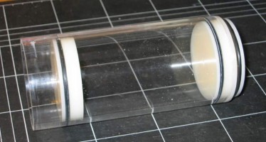
The piston is made from a Plexiglass tube and some acryl rod which of both a bought on Ebay.
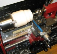
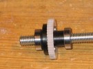
The piston is turned to shape on the lathe:
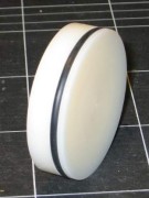
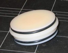
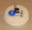
Here the piston the assembled, without the mechanics. The tolerance on the pistons groove for the O-ring is very small (app. 1/10 mm). It is a limbo to not making is to hard to move and at the same time make it watertight. (The first attempt didn't work). The other O-ring grooves have bigger tolerances as they should not be moved by a motor, but only pressed in by hand.
At the other end of the tube the motor is placed together with the gear, ball bearing etc.
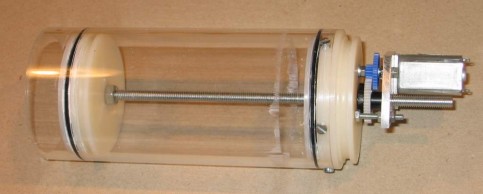
The piston with the motor attached:
The gear ratio used is app. 12:1 including the motor gear.The motor draws app. 1.3A at 6V and is about 10 seconds to move the piston from end to end (when there is no pressure).
Piston Test
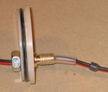
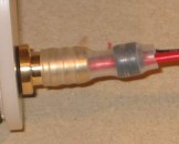
Now it was time to test if the piston was watertight. Before I could do that I needed a way to attach the wires to the motor in a airtight way. I took a small piece of brass, which I turned to the piece on the picture. The gray plastic on the wire is glued airtight with epoxy.
When the plastic part in inserted into the silicone tube it is air and water tight.
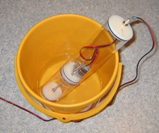
Now the piston the turned to the open position (water can enter the tube) and then the WTC is assembled. The WTC is then put into a bucket of water and then the piston is closed - which will force a vacuum in the WTC and in the piston (worse case scenario).
The piston is then moved back and forth a few times and then stand there for a couple of hours, and NO water enters the WTC :-)
The test also shows that the motor is using more power when under pressure - app. 2.5A compared to 1.3A with no load. It is also clear that if the pressure in the WTC is higher that outside, then the end caps will pop open, so they need to be secured later.
Here the whole tube is assembled and it is pressured tested with a manometer.
Piston position control
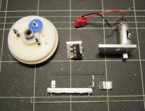
It is important that the computer system knows where the piston is to make the control better and also knows when it has reached the end. For that purpose a potentiometer is added along with a switch.
Even the spring is homemade!


